As an Amazon Associate, we earn from qualifying purchases. Some links on this site are affiliate links at no extra cost to you. Our recommendations are based on thorough research and editorial judgment.


How to Add a Switch to Battery-Operated LEDs

To add a switch to battery-operated LEDs, gather necessary components: an SPST switch, a compatible battery (e.g., CR2032), and a 100-ohm resistor. Drill a 1/2 inch hole for the switch. Connect the LED’s positive lead to one terminal of the switch, and the other terminal to the battery’s positive terminal. Attach the LED’s negative lead to the battery’s negative terminal. Guarantee secure connections and test the setup for proper functionality. Explore further steps to enhance your project.
Key Takeaways
- Choose an SPST switch that matches the LED voltage rating and connects to the battery for easy on/off operation.
- Connect the positive lead of the LED to one switch terminal and the other terminal to the battery’s positive terminal.
- Include a 100-ohm resistor in the circuit to regulate current and protect the LED from burnout.
- Ensure proper wiring and insulation to prevent short circuits, maintaining correct polarity throughout the setup.
- Test connections with a multimeter before powering on to verify voltage and continuity for bright, stable LED performance.
Understanding the Components Needed
You may be interested

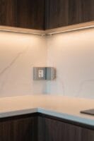

When considering the integration of a switch into battery-operated LEDs, it is essential to understand the components required for this project. An SPST (Single Pole Single Throw) switch is necessary for enabling easy on/off control of the circuit. The battery must match the LED’s voltage rating to prevent burnout; for example, a red LED typically operates efficiently at 2-3 volts. Additionally, using resistors, such as a 100-ohm resistor, can help regulate the LED’s current, ensuring its longevity and performance. A CR2032 coin battery, rated at 235mAh, is ideal for low-drain LED configurations. When wiring, connect the positive terminal of the battery to one terminal of the switch and the LED’s positive lead to the other terminal for proper function. For enhanced mounting stability, mounting bracket clips can secure the LED strips and prevent sagging while maintaining proper electrical connections.
Preparing the Box for Installation
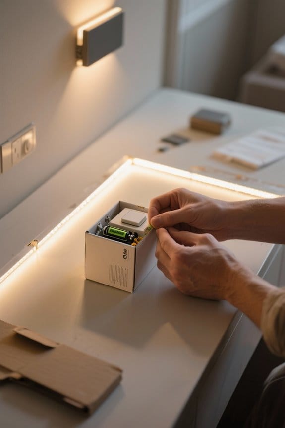
Start by drilling precise holes in the wooden box to securely mount the switch and LED. Verify these holes are appropriately sized for ease of access and operation, typically around 1/2 inch in diameter. Utilize a friction fit for the LED by accurately sizing the hole; consider using foam to stabilize the LED within the box. Next, prepare the interior for wiring by securing the battery holder in place, using screws or strong adhesive to prevent movement. Keep all connections insulated and well-organized to avoid short circuits, particularly around the switch and LED connections. Finally, consider sealing around the switch mount to protect internal components and maintain a clean, unobtrusive design in the finished project. The installation process is similar to mounting motion sensor lights which typically have a 120-degree activation angle for optimal functionality.
Recommended Products

Control 4 doors.Get in door by swiping card/key fob, inputting PIN code or using card + PIN, and get out door by pushing button. Can store/download/check entry records and generate report by professional management software.

MINIMALIST STYLE: This 54-inch indoor ceiling fan has 5 powerful blades to make your home more comfortable; It offers a sleek, minimalistic design that blends into any modern environment. With shapely, carved wood blades, this large ceiling fan offers an ideal blend of style and function.

Am/ FM aux-in 2. 1 Channel system featuring dual front firing speakers with enlarged magnets along with a rear passive subwoofer and Deep bass compensation in an acoustically tuned wooden cabinet for improved sound quality
Wiring the Switch and LED
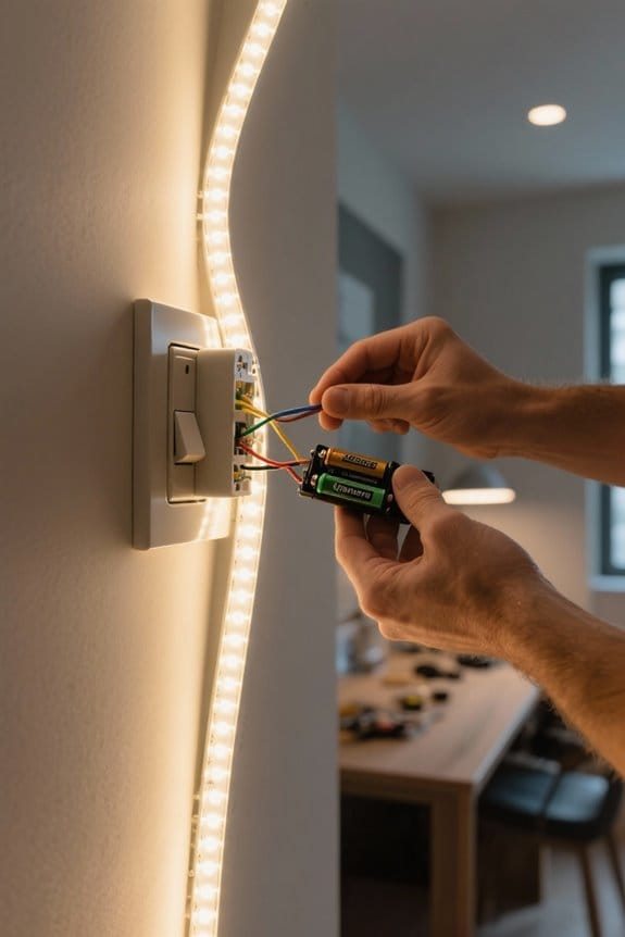
Wiring the switch and LED requires careful attention to detail to guarantee proper functionality and safety. Begin by connecting the positive lead of the LED to one terminal of the switch. The other terminal of the switch should connect to the positive side of the battery. This configuration allows the switch to control the LED effectively. Next, attach the negative lead of the LED directly to the negative terminal of the battery, ensuring a complete circuit. Utilize insulated wires throughout to prevent short circuits. If necessary, include a resistor to limit the current to the LED, ideally between 10-20 milliamps. Finally, verify the orientation of connections to prevent reverse polarity, thereby avoiding potential LED failure. For enhanced lighting control and aesthetics, consider housing your wiring inside anodized aluminum channels which protect against moisture and dust while providing effective heat dissipation.
Recommended Products

Selectable Wattage, 3CCT & 0-10V Dimming: This 2x4 LED flat panel light features selectable 30W/35W/45W power settings with 3300LM/3850LM/4950LM output, plus 3500K/4000K/5000K color temperatures. Designed as an energy-efficient replacement for traditional fluorescent troffers, it helps reduce energy use while allowing one fixture to replace multiple fixed-wattage or fixed-CCT options. Compatible with 0-10V dimmers for smooth brightness control in offices, classrooms, retail stores, and commercial spaces.

PORTABLE LIVE SONAR - Includes everything but the Display. Perfect for Ice Fishing, Canoeing, and Kayaking.

ADVANCED POWER DISTRIBUTION: Control up to eight 12V/24V circuits rated at 30 amps each with a compact, programmable power management hub designed for off-road and overland vehicle builds.
Connecting the Power Source
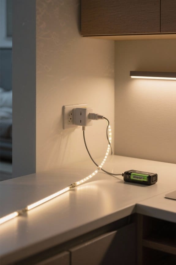
Connecting a power source to battery-operated LEDs requires meticulous attention to detail to verify peak performance. First, identify the positive terminal and negative terminal of both the battery and the LED. It is essential to maintain correct polarity during connections. Use a switch to turn the circuit on and off; connect one terminal of the switch to the battery’s positive terminal and the other to the LED’s positive lead. Confirm the LED’s negative lead connects directly to the battery’s negative terminal, completing the circuit. Additionally, include a resistor, typically around 100 ohms, in series with the LED to limit current and prevent overdriving. This guarantees that the light would operate efficiently while prolonging the LED’s lifespan. For optimal functionality, consider installing motion sensor capabilities that can detect movement within 10 to 120 degrees, providing convenient hands-free operation.
Recommended Products

This is a 1000w resistor that can be used for fast braking of 7.5kw VFD

【About Starter Kit】 ElecFreaks Micro:bit Starter Kit is designed for microbit beginer who is beginning learning electric circuit and programming knowledge. They can use this micro:bit basic DIY kits to create or complete more experiment, such as traffic light , use photocell to control mircro:bit screen or LED.

✔️12V LED load resistor for car tail lights and turn signals, made of high quality materials to sustain long lasting usage.
Securing the Battery and Components
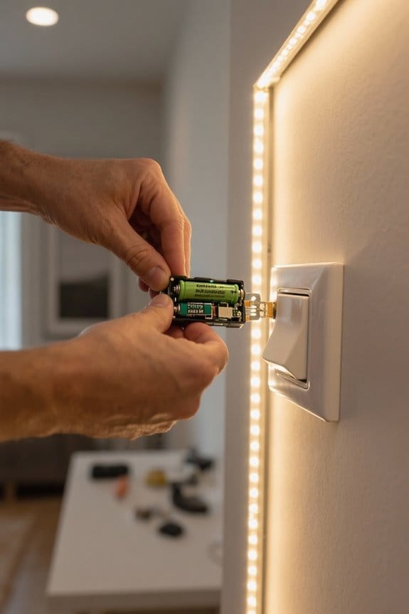
Securing the battery and components effectively is essential for the longevity and functionality of battery-operated LED projects. A battery holder can be employed to firmly secure a 2032 coin battery in a project box, enabling easy access for future replacements. Drill precise holes in the box for mounting components like switches and LEDs, ensuring a snug fit to prevent unwanted movement. To enhance stability, consider using small clamps or adhesive solutions to minimize rattling. Additionally, insulated wires should be employed to connect the components neatly, preventing short circuits and promoting proper functionality. Keep the design clean by limiting exposed components, ideally housing the main power supply and supporting elements within the box structure itself for a polished appearance. With proper installation, these LED systems can achieve 50,000 hour lifespans while maintaining consistent brightness levels.
Testing the Setup
Before testing the setup, it is critical to verify that all connections are secure, guaranteeing the circuit functions correctly. Check the positive lead from the battery to the illuminated rocker switch, and from the switch to the LED. Employ a multimeter to verify voltage and continuity in the circuit. This step confirms that the LED receives power when the switch is activated. For a rocker switch, verify the three pins are wired correctly: one to the battery’s positive terminal, one to the LED’s positive lead, and the third to ground. During the test, monitor the LED’s brightness to guarantee it receives approximately 2-3V, as specified. Flickering or failure to light indicates a need for connection verification or battery replacement. Installing energy-efficient LEDs can reduce power consumption by up to 80% compared to traditional lighting options.
Troubleshooting Common Issues
Even with a thorough setup and successful testing, issues may still arise when integrating a switch into battery-operated LEDs. In troubleshooting, first verify the switch’s specifications match the LED voltage, typically around 3V. Confirm that the positive terminal of the battery connects securely to one terminal of the switch, linking the other terminal of the switch to the LED’s positive lead. Always incorporate a 100-ohm resistor in series with the LED to prevent burnout. If flickering occurs, check all connections for tightness; loose wires interrupt power flow. Inspect for proper insulation to avoid short circuits that could damage components or cause safety hazards. Address these points diligently to guarantee reliable operation. Consider installing motion sensor capabilities to enhance usability and eliminate manual intervention while maintaining energy efficiency.
Recommended Products

HOME BACKUP POWER, ≤3% THD: The Westinghouse iGen12000TFc tri fuel inverter generator provides whole home backup power that's safe for sensitive electronics; It also has a 50A outlet; Gasoline: 12,000W peak/9,000W running; Propane: 11,000W peak/8,100W running; Natural gas: 9,800W peak/7,200W running

HUGE PORTABLE POWER: The WGen14500TFc tri fuel generator with CO sensor is an ideal power source for jobsites and emergency backup of larger homes. Gas: 18,000 peak watts, 14,500 running watts; Propane: 16,000 peak watts, 13,000 running watts; Natural gas: 14,400 peak watts, 11,600 running watts

【Grade-A LiFePO4 Cells & 100A BMS】This 48V 100Ah LiFePO4 battery is built for safety with a durable full-metal shell and a 100A BMS to protect it from overcharge, over-discharge, over-current, short circuit and high/low temperature, while cell balancing helps support long-term battery health.. It also integrates a 125A air switch and a battery power switch to ensure your system stays safe and secure under any conditions.
Alternative Power Solutions
Exploring alternative power solutions for battery-operated LEDs opens up opportunities for enhanced performance and longevity. For a more lasting power source, consider using two AAA batteries in parallel. This configuration provides stable power, prolonging the life of LED lights compared to smaller coin batteries, which often deplete quickly. Incorporating a switch, such as an SPST or SPDT, enables users to control their LED setup effectively. Additionally, using a resistor—such as a 100-ohm—for current regulation is essential; it keeps the flow within the recommended 10-20 mA range, protecting LED longevity and maximizing brightness. Alternatively, a 12V wall adapter can serve as a reliable power solution, eliminating frequent battery changes while maintaining consistent performance. For enhanced convenience and customization, implementing remote control operation allows users to adjust brightness levels from up to 20 feet away.
Tips for Efficient Usage
To achieve efficient usage of battery-operated LEDs, meticulous attention to wiring and component selection is essential. Connect the positive wire from the battery to one terminal of the switch, and link the other terminal to the LED’s positive side. This connection allows for proper activation. Incorporate a 100-ohm resistor in series with the LED, controlling current flow to prevent burnout while optimizing brightness. Typical LED current draw ranges from 10 to 20 milliamps. For better efficiency, use low-profile rocker or push-button switches to minimize power loss. When utilizing a CR2032 battery, consider its internal resistance which may limit current. Testing the entire circuit with all components connected can help identify wiring issues early in the assembly process. Similar to ETL certified strips, battery-operated LEDs can be customized by cutting to specific lengths for versatile installations.
Frequently Asked Questions
How to Connect a Switch to LED Lights?
Connecting a switch to LED lights involves using proper wiring techniques, selecting compatible battery types, and choosing the right switch types. Safety precautions are essential to guarantee secure connections and prevent potential hazards from improper installations.
How to Connect Two LED Lights to One Switch?
How can one effectively connect two LED lights to a single switch? A clear wiring schematic guarantees proper switch placement, maintains LED brightness, enhances battery life, and emphasizes essential safety precautions to prevent electrical issues.
How to Connect a Switch From a Battery?
To connect a switch from a battery, use wiring diagrams to understand switch types like inline switches. Adhere to safety precautions by ensuring proper battery connections, using appropriately rated switches, and insulating wires to prevent shorts.
Do LED Lights Need a Special Switch?
LED lights don’t demand a distinct switch; standard LED switch types suffice. However, switch compatibility factors, battery voltage considerations, circuit safety tips, and LED power ratings must be thoroughly evaluated for maximum functionality and safety.